Wednesday, July 31, 2013
Audi A4 B5 ABS Controller Pump Repair
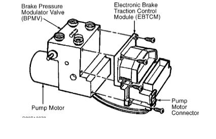
The ABS module is located under the hood on the driver’s side. It is composed of three parts, the Electronic Brake Traction Control Module, Brake Pressure Modulator Valve and the Pump. Most of the ills on the ABS system center on the Control Module. The Control Module houses the computer and electronics that make the ABS work. In fact, the Control Module does not even need any instruction from the main ECU to work. The only communication between the ECU and the Controller is to turn the ABS light on and off and to interface for Diagnostic Trouble Codes and testing functions. On cars with ESP, there is also a module under the back seat that monitors the yaw of the vehicle and can apply braking to any of the four wheels to control unstable handling conditions.
To troubleshoot the “ABS light on” condition do the following:
Connect the car to a VAG scanner. Select 03 for ABS Brakes controller. If you receive codes related to wheel sensors proceed with a wheel sensor diagnostics (not covered by this article). If there a problem with the control module you will most likely get a code like the following:
Control Module Part Number: 8E0 614 111 M
Component and/or Version: ABS/EDS 5.3 QUATTRO D31
Software Coding: 0273004134
Work Shop Code: BB 24302
1 Fault Found:
01203 - Electrical Connection between ABS and Instrument Cluster
03-10 - No Signal – Intermittent
Do not be fooled by the Instrument Cluster error. This not really the problem. I have read many posts on message boards about people spending a lot of money replacing the Instrument Cluster only to find it did not fix the problem.
Another error that you with a faulty Control Module is the following:
Control Module Part Number: 8E0 614 111 M
Component and/or Version: ABS/EDS 5.3 QUATTRO D31
Software Coding: 0273004134
Work Shop Code: BB 24302
1 Fault Found:
65535 - Internal Control Module Memory Error
35-00 - -
Once you have determined the ABS module is at fault you have three choices: Buy a new ABS unit, buy a used ABS unit, or have your current Control Module rebuilt. Audi does not sell the control unit by itself. You must purchase the entire unit Control Module, Pump and Valve assembly. In my case, for a “8E0 614 111 M”, the cost was $1950. This would also involve bleeding the whole brake system.[Editors note: It is possible to purchase the electronic part directly from Audi, but the cost is still higher than the cost of the options listed here.]
An easier, less expensive option is to purchase a used unit or get your Control Module rebuilt. In both cases, removing the Control Module and not breaking into the hydraulics is a more attractive option.
If you are purchasing a used unit, be aware the part number is very important, especially the last letter. Most of the Audi and VW Bosch 5.3 units start with the same nine numbers. There is some switching around of part numbers that can be done, but I don’t have any information on these options.
I successfully repaired my Control Module through a company in Florida called Auto and Truck Electronics (www.autoecu.com). The repair was $350 plus shipping. Be sure to call first to see if they can rebuild your controller before proceeding.
The module is not difficult to remove.
1. Jack up front left side of the car and support with a jack stand.
2. Remove the wheel.
3. Remove inner plastic fender liner. It is attached with 11 Torx head screws (T25).
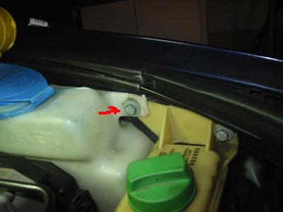
4. Remove the windshield washer bottle. It is attached by three 10mm screws. Two are accessible through the fender, and the other shares a screw with the power steering bottle. Also remove the hose between the other half of the windshield washer bottle. This will take a little tugging. Be sure to have a bucket ready!
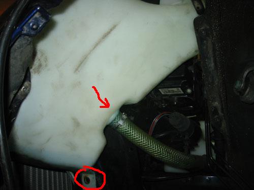
5. The ABS controller will now be accessible. Carefully remove the pump power wire from the bottom of the controller.
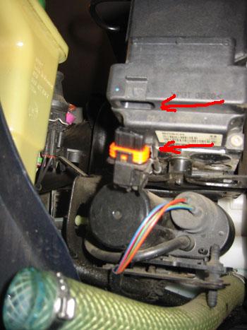
6. Remove the main harness connector from the ABS Module by pulling the connector pull shown.
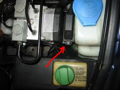
7. Separate the ABS Controller from Value/Pump assemble by unscrewing the six Torx screws (T20). Carefully remove.
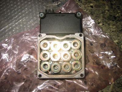
8. Prepare to the Module to ship by securing the solenoids so that they will not move around during shipping and wrap in something like bubble wrap.
9. After you receive the repaired Module back, assembly is the reverse of the previously detailed procedure.
10. After reinstallation, it may be necessary clear DTCs with a VAG scanner to clear the ABS light.

Sunday, December 2, 2012
get 2012 Audi A6 Quick Reference Guide

download here 2012 Audi A6 Quick Reference Guide
Download Audi A4 Avant Quick Reference

download here
Thursday, December 1, 2011
Audi RS4 Technical Training Manual
Audi RS4 Technical training guide is contain basic information of the Audi RS4 vehicle systems which needed for Audi Technician or Mechanical. Content Inside: Body, The Audi RS4 Slide, sills, front end, rear spoiler, brief summary, engine and gearbox, engine -RS1 crankcase/crank assembly, cylinder head, piston/con-rod, engine cooling system , injection system, fuel system, secondary air system, engine management, air
Audi Navigation System Manuals - Operating Instruction
This Audi Navigation system operating instruction covers complete information regarding how to use the Navigation system correctly. Content index: Display and operating elements, introduction, important notes, audi navigation plus, main screen, map and information display, switching the set on and off. Main navigation menu, edit menu, entering destination, special destination, destination memory. Radio, CD Charger, operating the television, switching on the television mode, video mode. Anti Theft Coding, guarantee, exchange, antenna care, registration. Index.
Audi A6 C5 Air Conditioner Output Diagnostic Testing
Component location of activated components, The Output Diagnostic Test Mode (DTM) can be carried out more than once if necessary. If components marked with an * malfunction, DTCs for these components can be stored in DTC memory. Checking the “Idle Air Control” (IAC) regulation function. During output DTM, the vehicle must not be moved and the engine speed must be lower than 3000 RPM. During output DTM, the air conditioning control functions are switched off. Depending on A/C Control Head -E87- version, all segments, control lights in buttons as well as the button illumination of - E87- are displayed or dark. For Audi allroad, the change-over of the A/C system is not performed with the model year change 2001 to 2002, instead it is a running change (implementation open, for vehicles with 4.2 Liter engine with start of production). A/C clutch -N25- - A/C clutch -N25- clicks every 2 seconds, compressor is engaged. - Input of A/C Control Head -E87- is closed every 2 seconds (switched to Ground). - Check voltage supply for A/C clutch - N25- (via clutch relay -J44-) according to wiring diagram. - Check wiring between -E87-, -J44- and -N25- according to wiring diagram. - Replace A/C control head - E87-. The ECM uses the A/C compressor cut in signal to compensate for the temporarily higher load placed on the engine when the compressor is switched on. The ECM can switch off the A/C compressor via the A/C compressor cut-in output/input ( Read measuring value block). Fresh Air Blower -V2- - Fresh Air Blower -V2 is activated for 2 sec. with 0V, 3V, 6V, 9V, 12V, 15V, 0V etc. -
Wednesday, November 30, 2011
Audi Air conditioning Does Not Cool Service Bulletin
This technical service bulletin is a simple document that explain step by step guide to troubleshoot your Air Conditioning on Audi Vehicle (does not cool), you’ll learn step by step explanation complete with illustration. Air conditioning doesn’t cool. Only 2006 and 2007 A3 models equipped with Zexel air conditioning compressors with the part number 1K0 820 803N are affected. This compressor type can be identified by the pulley shown in Figure 1. Technical Background: There may be one of two possible problems with Zexel air conditioning compressors. Obstruction: A/C compressor control valve N280 in the air conditioning compressor is obstructed by metal debris, and the compressor generates no pressure. With the engine running and air conditioning switched on, the center bolt (Figure 1, Point 2) doesn’t rotate
1998-2004 Audi A6/S6 Parts Manual
The parts manual/list document for Audi A6/S6 year 1998-2004, contain clear engine exploded views with number and part list. Section Index : A/C/Heater/Ventilation. A/C refrigerant capacities, ABS/Brakes, Air Bag system, Air Cleaner, Back Window, Conter console, clear coat identification, cooling, cowl and dash, cruise control system, electrical, emission control engine oil cooler,engine under cover engine/trans, front bumper, front door, front steering linkage/gead, front lamps, front seats, front suspension, fuel tank,roof, rear suspension, turbo charger/intercooler, underhood dimensions wheel, windshield and many
Audi S4 Engine Design and Function Study Guide
Turbocharged engines are already something of a tradition at AUDI. The task now facing AUDI’s engineers was to develop a worthy successor to the 5-cylinder turbocharged engine. One of the key development goals for the turbocharged engine was to achieve a good level of dynamic response, particularly at the bottom end of the rev band. The goal of AUDI’s engineers was to realise a igh “basic torque level“ and a torque characteristic that rises in direct proportion to engine speed to its peak. Engine: Technical data, crankshaft, cylinder head, camshaft timing, cooling circuit, engine lubrication, overview of components, air ducting, charging, exhaust system, pneumatically controlled systems,
Audi RS4 Engine Design and Function Study Guide
This is the Audi RS4 engine service/repair manual supplement which provide information on design and function for Audi engine and gearbox system such as: Engine -RS4, Crankcase/crank assembly, cylinder head, piston/conrod, engine cooling system, injection system, fuel system, secondary air system, engine management, air cleaner with additional air valve, intake air change-over valve, charge air cooler, gearbox. Running gear, front axle, rear axle, air conditioner, technical data. Repair measures: The engine removed together with the gearbox, in the case of a fault turbochargers mist always be replaced in pairs, The spark plugs must be replaced every 30,000Km
Tuesday, November 1, 2011
Audi A4 B5 Wiring Diagram
The wiring diagram of Bentley Audi A4 B5. Main fuse, Connector station E-box, plenum chamber, 4-Pin Relay Carrier with threaded connection, Fuse holder Fuse in fusebox from 23 onwards are numbered 223 onwards in Current Flow Diagram. 9-Pin Relay Carrier in the instrument panel. 4-Pin Connector, black, near front bumper. Ground strap, engine to body. Ground connection, in engine compartment, left. Ground connection
1998 Audi A6 Electrical Wiring Diagram - Full System
The electrical schematic / system wiring diagram of 1998 Audi A6 car, content Inside: Exterior lamp circuits chassis number 5000-5001, Ground Distribution Circuit, Air Conditioning Circuits, Anti-lock Brake Circuits, Anti-theft Circuit, Computer Data Lines, Cooling Fan Circuit, Cruise Control Circuit, Cruise Control Circuit, Defogger Circuit, Electronic Power Steering Circuit, 2.8L, Engine Performance Circuits, Back-up Lamps Circuit, Power Door Lock Circuit, etc. This wiring diagram available free to download in pdf format consists of 52 pages.
Monday, October 31, 2011
2003 A6 Spark Plug Replacement Procedure DIY Guide
This is a super easy project that will make you feel like you’ve done yourself a favor by keeping your money in your wallet while picking up a simple skill. From start to finish should take you under an hour - at most a two-beer job (if you’re thirsty). This was done on my 2003 A6 2.7T. I know the earlier years had coil packs that were bolted in. Not sure what other differences apply. Assemble the instruments of your endeavor. For this task, we’re going to use one flat head and one phillips head screwdriver, a 3/8 inch flex-handle ratchet with 18?. Using the phillips head screwdriver, remove the two